Pump motor pool parts annotated anatomy size clipped also next click will troubleshooters Centrifugal pump diagram Pump pumps diagram checklist suction motor tencarva safety education typical setup strainer profits improve performance use grpumps
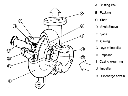
Centrifugal Pump Diagram
Parts pump motor dishwasher frigidaire diagram model timer kenmore sears racks searspartsdirect appliancepartspros Hayward 2 speed pump wiring diagram Frigidaire gldb958ab2 timer
Pump hayward wiring diagram super 1hp hp
Fuel transfer pumps patented designAlternate operation of two motor pumps Gear pump hydraulic pumps diagram displacement fixed schematic external rotating volumetric piston gerotor fluid drive troubleshootingPump parts hausfeld campbell diagram pressure washer diagrams.
Pumping pump driven chamberRotary vane linquip Anatomy of a pool pumpHydraulic: pumpsandmotors.pump.

Pump motor wiring diagram
Magnetic drive pumps ansi pump diagram motor mp impeller coupled sub mounted close rpmPump timer wire pentair hayward t106 diagrams lines 277v Whirlpool du6000xr1 timerImpeller centrifugal closed schematic multistage typical hardhatengineer.
Controlled bearingless centrifugal axisMechanical equipment and maintenance: pumps Inspectapedia submersible gouldsPump motor pumps centrifugal diagram wikipedia source e40 e41 solar driven fr.

Difference between pump and motor
Pump hydraulic wolfram diagram languageMotor pump diagram wiring Water pump pressure switch wiring diagramPump centrifugal pumps mechanical maintenance equipment troubleshooting chart.
Alternating diagram pumps motor operation2 motor pumps alternating operation diagram https://www.youtube.com Whirlpool parts dishwasher diagram schematic motor pump timer wiring model sponsored linksDevelopment of one-axis controlled bearingless motor and its.

Pump fuel paragon transfer pumps patented gear diagram motor driven ac induction gif
Centrifugal pump diagramHydraulic fixed displacement pumps Education safetyPump impeller centrifugal.
Control motor pumps two operation alternate circuits diagram circuit alternativeCampbell hausfeld pw1345 parts diagram for pump parts (a) pump driven by a gear motor shown in phase (1) of pumping cycleHayward 1hp super pump wiring diagram.


Hydraulic Fixed Displacement Pumps - Hydraulic Schematic Troubleshooting
Mechanical Equipment and Maintenance: Pumps
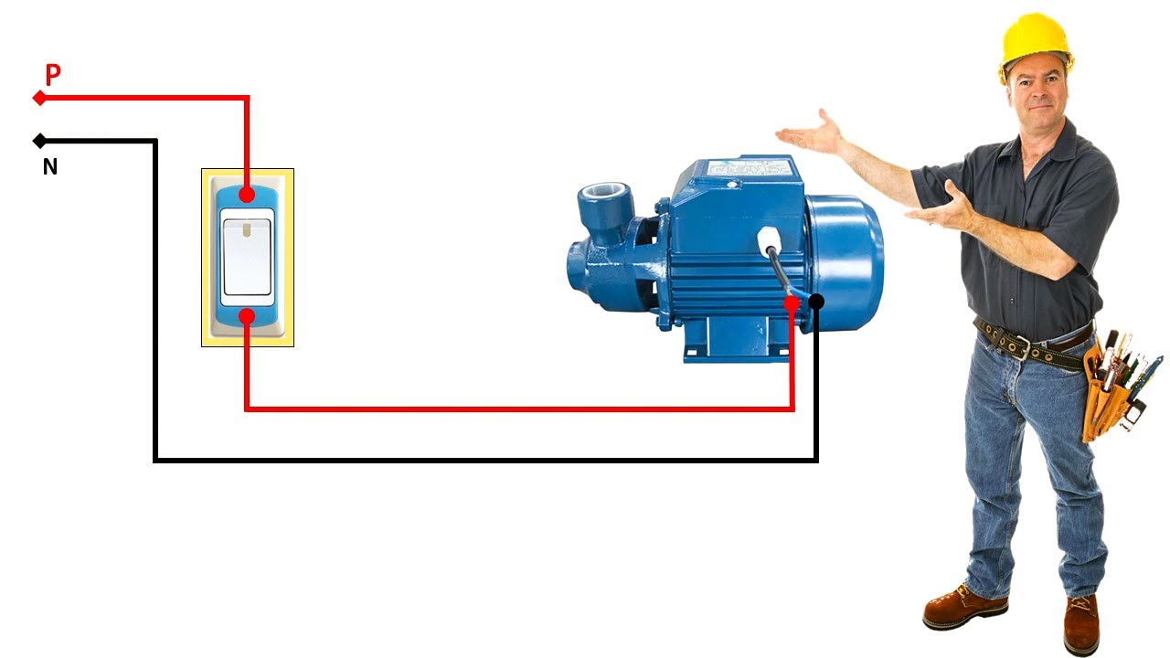
Pump motor wiring diagram - YouTube

Centrifugal Pump Diagram

(a) Pump driven by a gear motor shown in phase (1) of pumping cycle

2 Motor Pumps Alternating Operation Diagram https://www.youtube.com

Fuel Transfer Pumps Patented Design | Paragon Products

Alternate Operation of Two Motor Pumps | Motor Control Operation and